Due to issues with Blogger, pictures for this article can not be uploaded at this time. Please check again in the future.
If you have worked with blocks in AutoCAD, chances are you have worked with attributes. Most of the time attributes are visible, like when they are used for title block information or as tags. Attributes can also be invisible. An example use may be a model number or color of furniture. It's data that you may want, but is not necessary in a floor plan. That type of information will most likely need to show up in a schedule or a table. Today I'll show you how to extract that data directly to an AutoCAD table. It doesn't matter if your attributes are visible or not, I just want you to be aware that it's possible either way.
Once your attributed blocks are placed in a file you can extract that block data to tables or external files using the Attribute Extraction tool under the Tools pulldown. This simple wizard function walks you through the data extraction every step of the way with lots of great options like, dropping unattributed blocks, adding referenced blocks and nested blocks, and only use Model Space blocks.
In this example attributes from a door block will be extracted into a door schedule.
1. Under the Tools pulldown select Attribute Extraction…
2. The first page of this dialog gives you a choice between creating a table and using a template. For this first time we will create a table that we might later use as a template.
3. Next pick the data source to use either select some objects, the current drawing, or a group of drawings.
4. The Additional Settings… button allows you to select block and count settings.
5. Page 3 (below) provides options for which blocks and which attributes to use in the table.
On page 4 select export data to Table and check the full preview if you like
On page 5 select a title and a style for your table.
Page 6 allows you to save this configuration as a template or just finish your operation. See the final results below.
If you are feeling adventurous, add to this door schedule by using one of a formula field.
1. Double click in the bottom right cell of the schedule and hit tab key on your keyboard to add a new row to the schedule.
2. Double click in the bottom cell in the Quantity column.
3. Rick-click in the text editor and select Insert Field…
4. Select Objects for the Field category, and then select Formula for the Field name.
5. Average, Sum, Count, and Cell formulas are available.
6. Select Sum to return a total number of doors. You are returned to the drawing editor, window the cells to sum and hit Enter.
7. Select a format, and then select the OK button to insert the new field (see below).
The Average function will average the values in selected cells. The Sum function add the values in selected cells. The Count function will return the number cells selected. The Cell function will return the contents of a selected cell.
Now go eat a donut. With all the extra time you'll have from automatically extracting attributes, you'll probably need to join a health club.

Wednesday, May 31, 2006
Tuesday, May 16, 2006
Basic Lisp
There comes a time when you have done about all you can with AutoCAD menus and macros and you want to do more. I think we all know that means Lisp. Now just because you are great at design and understand computers, it does not necessarily mean you are a programmer.
That's OK.
Today I will be showing some basics of lisp. You might be surprised how easy Lisp is and how powerful you become with just a little information.
What is AutoLISP?
AutoLISP is a subset language of a high-level programming language called LISP. It allows users to write their own code to suit their own needs, and run it seamlessly inside of AutoCAD.
Programming Notes
Use Note pad, Word pad, or some other editing software. Do not use Word. It formats incorrectly and your lisps won't run.
Use indentations to clearly convey the meaning of your code. Even if the code is only for you, chances are you will revisit it infrequently. Clearly written code is much easier to understand and modify.
Do not reinvent the wheel. Start with similar code when ever possible and modify to suit your current needs. You can find lisp all over the internet.
Stick to your standards. Do not code similar tasks differently. Management becomes more difficult when you can’t remember how it was done in each individual instance.
Look for opportunities to create modular code. Write it once, and be done with it. I have a friend that wrote a small error handler module that would reset any varibles before it will allow an escape from the lisp it is run in. He attaches it to everything.
Create a “Test LISP” location. Debug enhancements to your current LISP routines before going live.
Think it through. Consider what the final output is, decide the best way to reach it, then code it.
AutoLISP code basics
Defun - Every AutoLISP routine defines a function using the defun command.
Parentheses - The number of open parentheses must match the number of closed parentheses.
Remarks - Use semicolons to indentify remarks in your code.
Here is a sample format for a simple lisp
; Name of LISP
; Date: x/x/x
; Revised:
; Written by: Cad Manager
; Description of what the lisp does
;
(defun Function Name (global variable /local variable)
(Body of lisp)
)
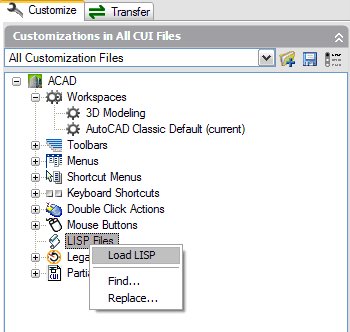
Ways to load LISP
Use the CUI command to automatically load your lisp file by right clicking on the word LISP Files
That's OK.
Today I will be showing some basics of lisp. You might be surprised how easy Lisp is and how powerful you become with just a little information.
What is AutoLISP?
AutoLISP is a subset language of a high-level programming language called LISP. It allows users to write their own code to suit their own needs, and run it seamlessly inside of AutoCAD.
Programming Notes
Use Note pad, Word pad, or some other editing software. Do not use Word. It formats incorrectly and your lisps won't run.
Use indentations to clearly convey the meaning of your code. Even if the code is only for you, chances are you will revisit it infrequently. Clearly written code is much easier to understand and modify.
Do not reinvent the wheel. Start with similar code when ever possible and modify to suit your current needs. You can find lisp all over the internet.
Stick to your standards. Do not code similar tasks differently. Management becomes more difficult when you can’t remember how it was done in each individual instance.
Look for opportunities to create modular code. Write it once, and be done with it. I have a friend that wrote a small error handler module that would reset any varibles before it will allow an escape from the lisp it is run in. He attaches it to everything.
Create a “Test LISP” location. Debug enhancements to your current LISP routines before going live.
Think it through. Consider what the final output is, decide the best way to reach it, then code it.
AutoLISP code basics
Defun - Every AutoLISP routine defines a function using the defun command.
Parentheses - The number of open parentheses must match the number of closed parentheses.
Remarks - Use semicolons to indentify remarks in your code.
Here is a sample format for a simple lisp
; Name of LISP
; Date: x/x/x
; Revised:
; Written by: Cad Manager
; Description of what the lisp does
;
(defun Function Name (global variable /local variable)
(Body of lisp)
)
Ways to load LISP
Use the CUI command to automatically load your lisp file by right clicking on the word LISP Files
Or just drag the lisp file from Windows Explorer into your AutoCAD drawing window. It will load on the fly, works great for debugging.
Code Examples
Example One
; Zoomout
; Zooms out by a factor of .5x
;
(defun C:zoomout ()
(command “zoom” “.5x”)
)
In this example the word defun tells AutoCAD a function is about to be defined.
The C: is telling AutoCAD what ever follows invokes the function when typed on the command line. So in this case, if you type zoomout, the lisp is executed.
The word command tells lisp to execute command line items that follow in quotes.
That's it. What can you write just knowing that?
Example Two
; Mysnaps
; resets the running osnaps to my favorites
;
(defun C:mysnaps ()
(command “’osmode” “183”)
)
Osmode is a system variable that defines what your running object snaps are set to. To find out what your osmode number is. Set your snaps and type osmode on the command line.
Example Three
; ArcEndDistance
; Invokes the arc command with the End and Distance modifiers
;
(defun C: ArcEndDistance ()
(command “arc” pause “end” pause “d”)
)
I introduced the pause command here which pauses the lisp for user input.
Example Four
; Centerline
; Changes the linetype of selected objects to centerline
;
(defun C: centerline ( / cl)
(princ “select objects to change to centerline linetype…\n”)
(setq cl (ssget))
(command “change” cl “” “prop” “LT” “center” “”)
)
This example introduces a variables and the ssget and setq functions. The ssget function is short for selection set get. The variable stores the selection set for future use. And setq sets the two equal. The princ command is also introduced, it will print text at the command line. The \n at the end is an enter to give the command line cursor a new line. Otherwise the cursor will sit at the end of the printed text.
Example Five
; D2R
; accepts number in degrees and returns equivalent radians
;
(defun D2R (a) This variable must be passed with the command D2R
(* pi (/ a 180.0))
)
Here is a little math in action.
Example Six
; MyClose
; Change current space to model, zooms extents, saves, then closes.
;
(defun myclose ()
(command “ctab” “model” “”)
(command “zoom” “e”)
(command “qsave”)
(command “close”)
)
Ctab is a system variable for current tab.
Use the Help function to fill in the blanks where you need help and modify these as you need to. There is a ton of Lisp on the internet for the taking. If you are lucky, you will never need to draw anything from scratch ever.
Subscribe to:
Posts (Atom)